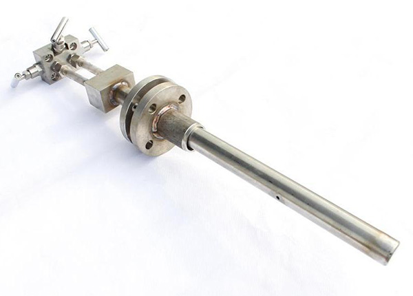
Velocity-equalizing tube flowmeter
One. Product overview
Velocity-equalizing tube flow sensorIs measured by differential pressure flow of the device, is on the basis of the pitot tube flow velocity measurement principle.Can measure the liquid, gas and steam flow of the fluid.With no moving parts, almost no pressure loss, easy installation and maintenance, operation cost is extremely low, favored by users.
Sensor is through testing rod, pressure and guide bar, it across with internal pipe axis vertical pipe, on the incident flow of rod is equipped with multiple pressure hole measured average total pressure, have to measure static pressure in the back and side stream surface pressure hole, respectively by the total pressure guide pipe and hydrostatic pressure derivation, according to the total pressure and static pressure differential pressure value, calculate the traffic flowing through a pipe.Can also substitute flow tube wall static pressure sensor on the surface of the back flow static pressure.
Velocity-equalizing tube flow transmitter consists of sensor, led accessories and differential pressure transmitter, pressure transmitter, pressure and flow totalizer.especially form a complete set of flow meter.
Velocity-equalizing tube flow sensor with my company production of differential pressure transmitter, pressure transmitter, temperature transmitter, and can be composed of various types of flow totalizer.especially velocity-equalizing tube flowmeter.Also can use any manufacturer production differential pressure transmitter, pressure transmitter, temperature transmitter and of various types of flow totalizer.especially velocity-equalizing tube flowmeter.
Second, the principle of work
Velocity-equalizing tube flow sensorIs based on the pitot tube principle of speed, it is the average velocity and pipe through the pipe flow of product to determine the effective cross-sectional area.
Average velocity distribution of pipe is not uniform.If it is a fully developed flow, the velocity distribution for the index law.Circular cross section in order to accurate measurement, the entire faceted and multiple unit area is equal to half more than half a ring.Sensor detection rod is composed of a hollow metal tube, flow surface of total pressure more holes, respectively in each unit area of the center of the reaction, respectively, the flow velocity of each unit area.Due to the total pressure hole is mutually, to each point in the detection lever average total pressure value, the total pressure out pipe leads to high pressure joint, the normal pressure chamber to the sensor.When the sensor is installed correctly on the process piping of straight section of long enough, traffic on the cross section should be no vortex, the whole cross section of the static pressure is constant, can be thought of in the back of the sensor or side is equipped with inspection hole, on behalf of the entire cross section of the static pressure.By the static pressure out pipe joint by low pressure leads to the negative pressure chamber of the transducer.The square of the positive and negative pressure chamber pressure differential is proportional to the flow of section average flow velocity, the cluster for differential pressure and flow rate is proportional to the relationship.On the relationship between the, can by the Bernoulli equation and continuity equation was derived velocity-equalizing tube flowmeter flow calculation formula
Qv = alpha, epsilon ﹒ ﹒ D2 (PI / 4), (2? P/rho (1) 0.5
Qm = alpha, epsilon ﹒ ﹒ D2 (PI / 4), (2? P ﹒ rho (1) 0.5
Qm: including: Qv: volume flow to mass flow
Alpha: sensor structure coefficient
Delta P: differential pressure value epsilon: fluid expansion coefficient
Rho: the density of fluid conditions epsilon: fluid expansion coefficient
For non-compressible fluid epsilon = 1, the compressibility of body epsilon ﹤ 1, if the type D, delta P, rho 1 use SI units, QV unit for the M3 / S, the basic unit of Qm is ㎏ / S.
Sensors of flow coefficient alpha and lessens epsilon, sexual coefficient can be informed by calibration on the standard device, and indicated in the certificate book when leaving the factory.
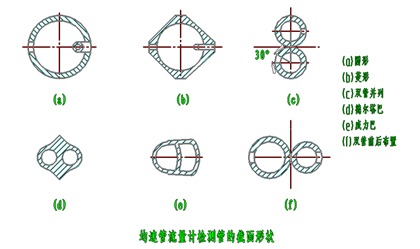
Third, the basic structure of the sensor, are shown in figure 1 below
Four, product selection
3.1, spectrum specifications
Spectrum specification | instructions | |||||||
ZY- | Average flow sensor | |||||||
The sensor type | HLV | Power of the flowmeter | ||||||
HLVD | The delta flowmeter | |||||||
ANB | Pig the flowmeter | |||||||
Medium type | Y | liquid | ||||||
Q | gas | |||||||
Z | steam | |||||||
The fluid temperature | 2 | < 200 ℃ | ||||||
5 | < 500 ℃ | |||||||
Fluid pressure | 1 | ≤1.6MPA | ||||||
2 | ≤2.5MPA | |||||||
3 | ≤4.0MPA | |||||||
4 | ≤6.3MPA | |||||||
5 | ≤10.0MPA | |||||||
6 | ≤25.0MPA | |||||||
Structure type | 1 | Ⅰ model, detailed in section 3.2.1 | ||||||
2 | Ⅱ type, see the section 3.2.2 | |||||||
3 | Ⅲ model, detailed in section 3.2.3 | |||||||
4 | Ⅳ model, detailed in section 3.2.4 | |||||||
5 | Ⅴ type, as shown in the detailed section 3.2.5 | |||||||
precision | 1 | 1.0 on the Richter scale, see section 3.2.8 accuracy table | ||||||
2 | Section 1.5, see detailed 3.2.8 accuracy table | |||||||
3 | 2.5 on the Richter scale, see section 3.2.8 accuracy table | |||||||
The connection method | 1 | Threaded connections | ||||||
2 | Flange connection | |||||||
CAL | S | Numerically, see section 3.2.6 sensor series of nominal diameter | ||||||
3.2, spectrum specifications
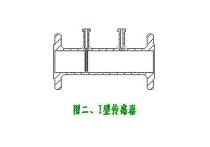
3.2.1, Ⅰ type, suitable for (20 ~ 50) ㎜ pipeline, appearance is shown in figure 2.The test bar diameter is 4.5 ~ 6.5 ㎜ commonly, sensors and pipeline connection has two kinds: one kind is threaded connection, the other is a flange connection.Used for high pressure measurement is used when the flange connection, as shown in the figure below
Due to the pipe diameter is not too big, in order to reduce the blocking to prevent interference, detecting the section size of rod should be small as far as possible.Generally no greater than 8 ㎜ in diameter.Take hydrostatic pressure tube changed back to the outside of the test bar.Three is shown in the diagram below
When measuring tube diameter larger, detection of rod cross section can be thicker, also won't flow field are disturbed.The general to take pressure tube on the incident flow on the back of the static pressure the total pressure in pressure pipe to form an organic whole, make the sensor play tightly, is conducive to install and maintain.When the pipe diameter is large, and the velocity is very high, one should be installed at the other end of the pipe diameter, strengthen rigidity.
Wide application scope of such a structure, disassembly is very convenient.When the flow velocity and high pressure measured medium, should be fixed on the pipeline flange connected to the sensor.

This kind of sensor applies to pipe diameter DN is greater than or equal to 1000 ㎜, pressure measurement of more than 20 mpa, because the flow velocity increases, acting on the fluid impact on test bar increased.In order to strengthen the rigid besides using flange connection, will also be bold to detect the diameter of the rod.This kind of sensor has unilateral and bilateral fixed fixed two types.
3.2.5, Ⅴ type, special type, is suitable for the dirty medium.When measured medium is dirty, in order to prevent hole plugging, equipped with reverse blow parts, may, when necessary, don't interrupt process using compressed air to blow.Blowing medium shall be the same with the medium in the pipeline, the pressure should be greater than the static pressure in the pipeline.
3.2.6, nominal size of sensor has the following series:
25, (32), 40, 50, (65), 80100, (125), 125, 0120, 0140, 0160, 0200, 0250, 0300 mm (number of parentheses is generally not recommended users choose)
3.2.7, nominal pressure of sensor has the following series: 1.6, 2.5, 4.0, 6.3, 10, 25 MPa.
3.2.8, sensor precision grade (see table below)
The accuracy level | 1.0 | 1.5 | 2.5 |
The basic error limits Ea | + / - 1.0 | + / - 1.5 | + / - 2.5 |
Repetitive % | 0.1 | 0.2 | 0.5 |
3.3 use requirement
3.3.1, by measurement of body shall be full of pipe flow and stability.
3.3.2 rainfall distribution on 10-12, measured the fluid should be single phase, the phase constant, for
Components of complex fluid must be similar to a single component of fluid can be used.
3.3.3, be flow under actual conditions of ReD should be greater than 3 x 10⁴
We do, should guarantee the sensor before and after the straight pipe length requirements.
3.3.5, pipe diameter greater than 100 ㎜ as well.
3.3.6, 2 d in front of the sensor on the surface of the pipe, should be clean and smooth.
Five, installation and maintenance
4.1, installation requirements
4.4.1, for sensor type I, have set up test lever and a pipe welding as a body, when installation, must make the sensor in the direction of fluid flow.The inner diameter of the inside diameter of process piping and sensor, or at least in the straight pipe upstream of the required length within the scope of the axis of the sensor with the pipe axis Angle as far as possible to zero.
Other types of sensor is the detection of rod inserted into the process piping, in addition to the total pressure hole when installation should is opposite flow direction, must ensure that the sensor detection pole perpendicular to the axis of the process piping, which allows the location of the pressure Angle deviation is shown in figure 5.
Total pressure sensor hole center and the pipe axis Angle should be less than 7 °
Sensors pole along the direction of the pipe diameter inserted to the bottom, the angular deviation is less than 7 °
For vertical pipe sensor can be installed in any position along the pipeline circumferential 360 horizontal pipeline, high pressure pipe should be in the same plane, as shown in figure 6 (a);When measuring the liquid should be installed side tilt down as shown in figure 6 (b);When measuring gas steam should be upward sloping installation as shown in figure 6 (c)
.
4.1.2 straight pipe
Because of the sensor is based on velocity area method, using the approximate integral theory, use more points to describe.
Distribution equation, and is established under the condition of the full development of the velocity distribution.So, in order to get an ideal distribution, must be in before and after the sensor has a certain length of straight pipe section (see table below)
6. The product installation position description:
The serial number | Velocity-equalizing tube flow sensorInstallation position | Upstream side A | The downstream side of the B | ||
A rectifier | Without a rectifier | ||||
The same plane | Different plane | ||||
1 | There is a 90 ° elbow and tee | 6D | 7D | 9D | 3D |
2 | In the same plane with two 90 ° bend | 8D | 9D | 14D | 3D |
3 | In different plane with two 90 ° bend | 9D | 19D | 24D | 4D |
4 | Pipe diameter change (or expand) | 8D | 8D | 8D | 3D |
5 | Partially open gate valves, ball valves, or other throttle valve | 8D | 8D | 8D | 3D |
Note: (1) the "D" as the pipe diameter.
(2) in the case of insufficient pipeline section, shall be accounted for 70% of the total length of pipe upstream, downstream accounted for 30%, while still can give a steady value, but the accuracy of decline.
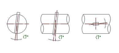
Figure 5 shows, velocity-equalizing tube installation location deviation
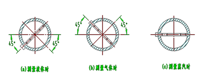
Figure 6
4.2 maintenance
2 sensors should be performed in the process piping overhaul regular cleaning, there are a number of ways for cleaning, such as air blow test tube accumulated filth;Scrub with kerosene and soft silk net, make each hole to maintain patency.
7. Product causes of failure and cleared
The serial number | The fault phenomenon | The causes of | Clear way |
1 | No differential pressure signal output | 1, high and low pressure valve is not open | 1, open the high and low pressure valve |
2, high and low pressure balance valves not tighten | 2, tighten the balancing valve | ||
2 | The differential pressure signal output is too small | 1, guide pressure system have leakage phenomenon | 1, serious search, eliminate leakage |
2, the second table improper range selection | 2, uninteresting facts limit pressure transmitter | ||
3 | The differential pressure signal output is too large | 1, the second table range selection | 1 the upper limit, augmenting the differential pressure transmitter |
2, back pressure hole plug | 2, cleaning velocity-equalizing tube, eliminate congestion |
Eight, velocity-equalizing tube smart meter supporting scheme selection
5.1.1 Velocity-equalizing tube flow sensor.According to the measurement of the medium and the user use the pipe inner diameter, working temperature, working pressure and flow change velocity-equalizing tube flow sensor design and production
5.1.2 3351/1151 dp series of differential pressure transmitter or other types of differential pressure transmitter
5.1.3 pressure transmitter, or other type of pressure transmitter
5.1.4 ensuring SWB series temperature transmitter, or other type of temperature transmitter
5.1.5 or other types of flow totalizer.especially flow integrating instrument
Of this intelligent velocity-equalizing tube flowmeter, with temperature compensation, and can show the instantaneous flow and cumulative flow medium medium temperature, the pipe, the pipe pressure and differential pressure equivalent, equipped with communication interface and 4 ~ 20 ma output.


